A roadmap of 3D printing technologies
3D printing is growing. Fast. The application of this concept is already quite vast, to say the least, so a clear overview gets messy very quickly. To increase the trouble, the whole field is seeded with fancy acronyms that mean little to nothing to the novice (FDM, EBF3, DMSL,…), and much less once one gets to know what they stand for (Fused Deposition Modeling?, Electron Beam FreeForm Fabrication?, Direct Metal Laser Sintering?…ahem, sorry what?).
For these reasons in this post we have chosen to make a little roadmap that will at least serve to the reader as quick visual reference in order to be able to get started without getting dazzled.
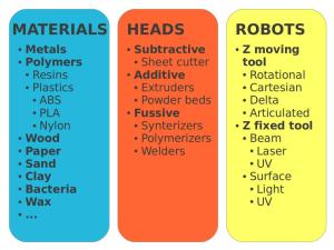
In general, there are three basic groups of ideas to dive in: Materials, Robots and Tools.
- Materials: The type and form of the materials define pretty much what can and what cannot be done with a 3D printing machine. Materials come in the shape of liquid, powder, pellets or filament, so the particular machine will deal with this in one way or another. Some materials, like for example resins, can only be treated from their liquid state, whereas plastics may come in pellets, in powder or as filament rolls.
- Heads: The head of the printer is the actual tool that in one way or another transforms the raw material into our 3D model. It can be an extruder, a laser device, an electron beam cannon, a UV cannon or a drill. Depending on what material and in what state it is that it is applied to, different techniques arise. For example, sintering uses a beam (of electrons, UV rays or laser) on very thin successive layers of powder to fuse those particles that lie under the beam, while an extruder deposits layer after layer of already molten material.
- Robots: In this article we will refer to the robot as the set of mechanisms that are accessory to move the actual head. This is normally the bulk of the printer, and includes not only the hardware (electronics, mechanics, etc…) but also needs some software to convert the data given in the form of a sliced 3D CAD model into pulses and motor rotations. The main difference among them lies in the way they manage the Z coordinate of the movement: either by moving the working base or by moving the head up-down. Sintering machines normally leave the head stationary in Z, progressively sinking the model in the liquid or powder, and also when the head is a cutter shaping successive laminae.

The three dimensions of 3D printing: Materials, heads and robots. Most of the terminology derives from the type of head, but also the type of robot and material are important to understand a particular type of printer.
In future posts we will be reviewing different techniques and printers, so we will be using this map to serve us of orientation.
Happy printing!


