Street Jacket prototype
In this post we are introducing the guts of our Street Jacket, inspired in Leah Buechley’s instructable (http://www.instructables.com/member/leahbuechley/).
The controlling part is based in an Arduino Micro, instead of her Arduino Lilypad. Other than a slightly higher price (Lilypad: 19€; Micro: 18€), Lilypad has half the memory and clock speed and less input pins, not to mention a high sensitivity to input voltage and no USB connection. On the other hand, Lilypad uses less battery, its round shape is optimized for attaching conductive thread with less pain and is waterproof and washable. In our case, we chose power and versatility over convenience as the tiny size of the Arduino Micro is still open to plenty of technical possibilities to overcome the advantages of the great Lilypad.


The Fritzing diagram below shows how to setup the electronic components that will be attached to our jacket:

Fritzing diagram
It consists of sixteen LEDs paired in two groups: one for signaling left and the other for the right. These are directly connected to the digital pins #2,#3,#4, #5 and #8, #9, #10, #11 of our Arduino, respectively, with a voltage controlling resistor in between. The mission of the resistors is to dissipate the extra power that might get to our sensitive LEDs and avoid having them fried.

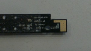
A Hall effect sensor with legs for sewing
Another important element is the pair of Hall effect sensors: again, one for the left and another for the right. They switch on or off in the proximity of a magnetic field. We found them in Farnell for 0,77€ a piece, which makes them very affordable (http://es.farnell.com/honeywell-s-c/ss460s/sensor-hall-effect-bipolar-to-92/dp/2301768). It is very important to choose the right case, with long legs, so later we can comfortably attach them to the clothes by simply twisting them. SMD cases need soldering and this can be tricky given their tiny size! These sensors have only two positions: On and OFF, HIGH and LOW, 0 and 1, acting as a simple switch that our Arduino’s digital sensors can easily read and interpret. Pay attention to the resistors connecting the legs!
Once the machinery is up and ready, we need to program our Arduino to control the beast. For the sake of simplicity, we have chosen Ardublock for such purpose. Put in the creator’s own words: Ardublock is a graphical programming environment to make programming physical computing with Arduino as easy as drag and drop. It is actually an extension of Arduino IDE’s, and comes in the flavor of a tool. In their own webpage they present a very good starting point: http://blog.ardublock.com/engetting-started-ardublockzhardublock/. The code below is Ardublock’s text version of the image below. Evidently, for those less familiar with structured coding visual programming has a lot of advantages!
void __ardublockDigitalWrite(int pinNumber, boolean status)
{
pinMode(pinNumber, OUTPUT);
digitalWrite(pinNumber, status);
}int _ABVAR_5_;
int _ABVAR_6_j;
int _ABVAR_2_i;
int _ABVAR_1_;
int _ABVAR_4_;
int _ABVAR_7_;
int _ABVAR_3_;void setup()
{
pinMode( 12 , INPUT);
_ABVAR_6_j = 0;
_ABVAR_2_i = 0;
pinMode( 13 , INPUT);
}void loop()
{
if (digitalRead( 12))
{
}
else
{
for (_ABVAR_1_=0; _ABVAR_1_< ( 5 ); ++_ABVAR_1_ )
{
_ABVAR_2_i = 2 ;
for (_ABVAR_3_=0; _ABVAR_3_< ( 4 ); ++_ABVAR_3_ )
{
__ardublockDigitalWrite(_ABVAR_2_i, HIGH);
delay( 10 );
__ardublockDigitalWrite(_ABVAR_2_i, LOW);
_ABVAR_2_i = ( _ABVAR_2_i + 1 ) ;
delay( 300 );
}}
}
if (digitalRead( 13))
{
}
else
{
for (_ABVAR_4_=0; _ABVAR_4_< ( 5 ); ++_ABVAR_4_ )
{
_ABVAR_2_i = 8 ;
for (_ABVAR_5_=0; _ABVAR_5_< ( 4 ); ++_ABVAR_5_ )
{
__ardublockDigitalWrite(_ABVAR_2_i, HIGH);
delay( 10 );
__ardublockDigitalWrite(_ABVAR_2_i, LOW);
_ABVAR_2_i = ( _ABVAR_2_i + 1 ) ;
delay( 300 );
}}
}
_ABVAR_2_i = 2 ;
_ABVAR_6_j = 8 ;
for (_ABVAR_7_=0; _ABVAR_7_< ( 4 ); ++_ABVAR_7_ )
{
__ardublockDigitalWrite(_ABVAR_2_i, HIGH);
__ardublockDigitalWrite(_ABVAR_6_j, HIGH);
delay( 10 );
__ardublockDigitalWrite(_ABVAR_2_i, LOW);
__ardublockDigitalWrite(_ABVAR_6_j, LOW);
_ABVAR_2_i = ( _ABVAR_2_i + 1 ) ;
_ABVAR_6_j = ( _ABVAR_6_j + 1 ) ;
delay( 300 );
}}
…is the same as this:

Naturally, the automatically generated code could be a bit more neat also, particularly in terms of tabulation, but in any case the application works very well for helping beginners to visualize what is going on…
So, here it goes…A bare bones Hall effect switched blinking machine!
Enjoy and happy tinkering!